

In this tutorial, learn how to interface IR sensor module with Arduino or ESP8266 or ESP32 to build an accurate Tachometer which measures RPM of a rotating object and display the measured values on 16×2 LCD display module. This cheap DIY IR based Tachometer is accurate than other laser based Tachometers which comes under the range of 50$ in the market.
Table of Contents
What is Tachometer and RPM?
The tachometer is nothing more but measuring instrument that is used to measure rotating elements, to determine the number of turns that it makes on its own axis in certain amount of time, which depends on its speed.
The unit of measurement of the tachometer is the revolutions per minute (RPM), since you have to understand that revolutions mean turns, then it would be the number of turns that the element makes, for each minute.
The word tachometer has an origin in the Greek vocabulary, the prefix “Tacko” means speed or high speed and for its part, the suffix “Metron” is translated as measure. So, this is why I affirm that the tachometer is an instrument that measures speed.
Working of IR sensor module

This DIY Tachometer is cheap and works with the principle of Infrared waves. Infrared waves has wavelength longer than the visible light, so they are not visible to our human eyes.
Here we are using an IR sensor module which contains two IR LEDs, one is to emit the IR rays which is called IR Transmitter, and another IR LED which is also called as IR Photo Diode which acts as a IR rays receiver or IR sensor.
IR transmitter LED looks same as normal LED but the IR rays emitted through it are not visible to human eyes, and IR receivers comes in the forms of photo diodes which are not same as normal Photo diodes as IR diodes receive only InfraRed rays.
When the IR sensor module is powered on, IR transmitter emits IR rays and reaches to an object in front of it and few amount of IR rays are reflected back and according to the intensity of the received rays the IR receiver receives the IR rays and generate the voltage and outputs it through the OUT pin with the help of LM358 IC.
DIY Tachometer to Measure Accurate RPM using Arduino
In this method we are using Arduino to build the tachometer by interfacing it with IR sensor to calculate the RPM to display the RPM on 16X2 LCD display module with I2C adapter. Lets look at the required component and build it according to the Circuit diagram below.
Required components:
Here are the required components along with Amazon buying links at best prices.| Product Name | Quantity | ||
|---|---|---|---|
| Arduino UNO board | 1 | https://amzn.to/3H4cKxZ | https://amzn.to/3638aTS |
| IR sensor module | 1 | https://amzn.to/3CrkeL0 | https://amzn.to/3sUg5vY |
| 16X2 LCD display module | 1 | https://amzn.to/3I3Uaax | https://amzn.to/363ki7F |
| Few Connecting Wires | https://amzn.to/3H2BV4e | https://amzn.to/3J0WVu2 | |
| ESP32 (For ESP32 Version only) | 1 | https://amzn.to/36gKUlu | https://amzn.to/3Kw2np2 |
| ESP8266 NodeMCU(for Its version only) | 1 | https://amzn.to/3tqMwkB | https://amzn.to/3sVdSjG |
Circuit Diagram interfacing Arduino and IR sensor module:
Connect all the Required components as shown in the below Schematic diagram.

From the above wiring diagram you can see the IR sensor and LCD display VCC and GND are powered from 5V and GND pins of Arduino respectively. The OUT pin from the IR sensor module is connected to the digital pin 2 on Arduino. SDA and SCL pins from the LCD display are connected to A4 and A5 of Arduino respectively. That’s it for connection now lets upload the below code and see how this works below.
To connect the LCD display without I2C refer:
Source code:
After connecting all the components as explained above now copy the below code and paste it in Arduino IDE and Upload to Arduino after selecting the board as Arduino UNO and correct port number which you can get through device manager of your PC.
To download LiquidCrystal_I2C library click : Libraries
//DIY Tachometer to Measure Accurate RPM using Arduino
//DIY Tachometer to Measure Accurate RPM using Arduino
//This code is published by https://www.circuitschools.com
//Attribution required to republish.
#include <LiquidCrystal_I2C.h>

// Create the lcd object address 0x27(get it from i2cscanner) and 16 columns x 2 rows
LiquidCrystal_I2C lcd (0x27, 16,2); //
float value=0;
float rev=0;
int rpm;
int oldtime=0;
int newtime;
void isr() //interrupt service routine
{
rev++;
}
void setup()
{
lcd.init (); //initialize LCD
// Turn on the backlight on LCD.
lcd. backlight ();
attachInterrupt(digitalPinToInterrupt(2),isr,RISING); //attaching the interrupt
}
void loop()
{

delay(1000);
detachInterrupt(0); //detaches the interrupt
newtime=millis()-oldtime; //finds the time
int wings= 3; // no of wings of rotating object, for disc object use 1 with white tape on one side
int RPMnew = rev/wings; //here we used fan which has 3 wings
rpm=(RPMnew/newtime)*60000; //calculates rpm
oldtime=millis(); //saves the current time
rev=0;
lcd.clear();
lcd.setCursor(0,0);
lcd.print("___TACHOMETER___");
lcd.setCursor(0,1);
lcd.print( rpm);
lcd.print(" RPM");
lcd.print(" ");
attachInterrupt(digitalPinToInterrupt(2),isr,RISING);
}
Working of IR tachometer:
After uploading the code when this device is powered on the, IR sensor’s IR transmitter transmits the IR rays and when an object comes in front of the sensor at a certain distance which can be adjusted with the help of onboard 1k potentiometer, these rays will get reflected back to the sensor photo diode which receives only IR waves and generates a voltage signal which outputs through the output pin as digital output with the help of LM358 IC.
According to the IR sensor working when an object comes in front of the emitted rays the sensor detects it as an obstacle and signal led lights up, and outputs a signal through OUT pin. When a rotating object rotates, for example a fan which has 3 wings rotates if we place the sensor in front of the rotating wings the sensor detects the wings and we can count the number of times the wings comes as obstacle before the sensor.
This output pin is connected to one of the digital pins of Arduino, with the help of interrupts and calculating the time, we can get the RPM value of the rotating object.
NOTES:
If you are using the disc type rotating object with black or other color other than white use a white tape as shown in the below image

This IR sensor is light sensitive so, it may give errors in high lighting conditions.
Output:
You can see the below out on the LCD display module

DIY Tachometer to Measure Accurate RPM using ESP32 or ESP8266.
In this method principle and working of the device is same except the interrupts and wiring. The interrupts which we used in the above Arduino example doesn’t work with ESP 32 and ESP8266( NodeMCU, Wemos D1. etc.) . So below you can get the wiring diagrams and source code which you can use to get the accurate RPM readings from the rotating objects.
First lets learn for ESP32
DIY Tachometer to Measure Accurate RPM using ESP32
Here we are using ESP32 instead of Arduino and ESP 32 has different type of interrupts than Arduino so the source code differs slightly than with Arduino. Through this we can measure the Revolutions per second and Revolutions per minute (RPM) of the rotating objects. This device gives stable results.
Circuit Diagram Interfacing ESP32 with IR sensor and LCD display
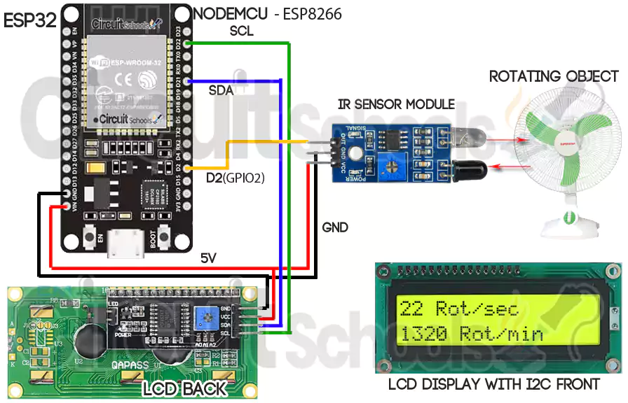
From the above wiring diagram you can see the IR sensor and LCD display VCC and GND are powered from 5V and GND pins of ESP32 respectively. The OUT pin from the IR sensor module is connected to the digital pin D2 (GPIO2) on ESP32. SDA and SCL pins from the LCD display are connected to D21 and D22 of ESP32 respectively. That’s it for connection now lets upload the below code to make it work.
To connect the LCD display without I2C refer:
Interfacing 16X2 LCD Module with ESP32 without I2C
Source code:
After connecting all the components as explained above now copy the below code and paste it in Arduino IDE and Upload to ESP32 after selecting the board as ESP32 Wrover board and correct port number which you can get through device manager of your PC.
To download LiquidCrystal_I2C library click : Libraries
//DIY Tachometer to Measure Accurate RPM using ESP32
//This code is published by https://www.circuitschools.com
//Attribution required to republish.
#include <LiquidCrystal_I2C.h>

// Create the lcd object address 0x3F and 16 columns x 2 rows
LiquidCrystal_I2C lcd (0x27, 16,2);  //

unsigned long lastflash;
int RPM;
void ICACHE_RAM_ATTR sens() {
  RPM++;
}

void setup() {
Serial.begin(9600);
lcd. init ();

  // Turn on the backlight on LCD.
  lcd. backlight ();

// IR Infrared sensor
pinMode(2, INPUT_PULLUP);
attachInterrupt(digitalPinToInterrupt(2), sens, RISING);
 //SENSOR: GPIO0 (NodeMCU - D3)
}

void loop() {
  noInterrupts();
  int wings= 3;  // no of wings of rotating object, for disc object use 1 with white tape on one side
  int RPMnew = RPM/wings;  //here we used fan which has 3 wings
  Serial.print(RPMnew);
  Serial.print(" Rot/sec :");  //Revolutions per second
  lcd.clear();
  lcd.print(RPMnew);
  lcd.print("Rot/sec");
  Serial.print((RPMnew*60));
  Serial.println("Rot/min. ");   //Revolutions per minute
  lcd. setCursor (0, 1);
  lcd.print(RPMnew*60);
  lcd.print("Rot/min");
  RPM=0;
  interrupts();
  delay(1000);  //1 second.
}
After uploading the code the IR sensor reads the Rotations per second and Rotations per minute(RPM) and display those values on to the LCD display as shown from the above diagram.
DIY Tachometer to Measure Accurate RPM using ESP8266 – NodeMCU
This method is same as above ESP32 and this also measures the Revolutions per second and Revolutions per minute (RPM) of the rotating objects. This device also gives stable results. the only thing which differs from the ESP32 method is the Wiring which you can get from the below circuit diagram.
Circuit Diagram Interfacing ESP8266-Nodemcu with IR sensor and LCD display
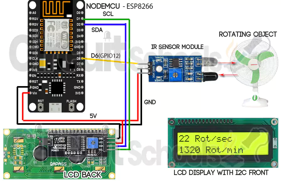
From the above wiring diagram you can see the IR sensor and LCD display VCC and GND are powered from 5V and GND pins of ESP8266 respectively. The OUT pin from the IR sensor module is connected to the digital pin D6 (GPIO12) on ESP8266-NodeMCU. SDA and SCL pins from the LCD display are connected to D2 and D1 of ESP8266-NodeMCU respectively. That’s it for connection now lets upload the below code to make it work.
Source code:
After connecting all the components as explained above now copy the below code and paste it in Arduino IDE and Upload to NodeMCU after selecting the board as NodeMCU 1.0 and correct port number which you can get through device manager of your PC.
To download LiquidCrystal_I2C library click : Libraries
//DIY Tachometer to Measure Accurate RPM using ESP8266 - NodeMCU
//This code is published by https://www.circuitschools.com
//Attribution required to republish.
#include <LiquidCrystal_I2C.h>

// Create the lcd object address 0x3F and 16 columns x 2 rows
LiquidCrystal_I2C lcd (0x27, 16,2);  //

unsigned long lastflash;
int RPM;
void ICACHE_RAM_ATTR sens() {
  RPM++;
}

void setup() {
Serial.begin(9600);
lcd. init ();

  // Turn on the backlight on LCD.
  lcd. backlight ();

// IR Infrared sensor
pinMode(12, INPUT_PULLUP);
attachInterrupt(digitalPinToInterrupt(12), sens, RISING);
 //SENSOR: GPIO0 (NodeMCU - D3)
}

void loop() {
  noInterrupts();
  int wings= 3;  // no of wings of rotating object, for disc object use 1 with white tape on one side
  int RPMnew = RPM/wings;  //here we used fan which has 3 wings
  Serial.print(RPMnew);
  Serial.print(" Rot/sec :");  //Revolutions per second
  lcd.clear();
  lcd.print(RPMnew);
  lcd.print("Rot/sec");
  Serial.print((RPMnew*60));
  Serial.println("Rot/min. ");   //Revolutions per minute
  lcd. setCursor (0, 1);
  lcd.print(RPMnew*60);
  lcd.print("Rot/min");
  RPM=0;
  interrupts();
  delay(1000);  //1 second.
}
After uploading the code the IR sensor reads the Rotations per second and Rotations per minute(RPM) and display those values on to the LCD display as shown from the above diagram.
If you find this project helpful please share it with your friends, and if you have any doubts or got any issues regarding this project please feel free to comment below or ask us on Facebook community page “Circuit Schools“. Your interest makes us happy and help to add more projects. Thanks and happy creations.


Thank you so much for adding the code for ESP32, I searched a lot but dint found a working code, but when I added your code on Arduino IDE and compiled gave 0 errors, and I am getting stable results but are those accurate?
Thanks,
william
Hi i need help, ho did u compiled the code. I add the code and gave me 0 errors but it didnt work it.
Piter
Same bro
sangat keren,.saya sangat suka postingan ini, bantu saya untuk menambahkan pin out on/off saat value TDS di bawah 1000 mpa
Do you test these files before you post them? The Arduino file does not work. the first problem is there are no comment // on the first line in the code, the second problem is the LCD address in the code is different in the comment (0x3F) and where it is called out in the file (0x37). Once I got the LCD working. the code does not read RPM.
would you please let me know what i have done incorrect
//DIY Tachometer to Measure Accurate RPM using Arduino
//This code is published by https://www.circuitschools.com
//Attribution required to republish.
< **** CODE ****>
Updated few lines of code and tested on ArduinoIDE and got 0 errors, please check again and if you still found any errors, please let us know we will fix as soon as possible.
Thanks
Circuitschools Team.
Some minor changes are needed to make this work.
In Arduino code, you have declare ‘RPMNew” as float instead of int. Otherwise when the RPMnew is divided by duration in milliseconds (which will be around 1000 milliseconds), it will result in 0 instead of a floating point fraction. (resulting in rpm as zero)
Esp32 WROOM 32:
Delete nointerrupt() and interrupt() statements.
Pin 2 was not pulling up all the way for me, not sure if it’s damaged but pin 4 worked. (Need to change pin # in pinmode and attachinterrupt statements).
Also changed RPM variable definition to “volatile int RPM” and icache_ram_attr to iram_attr.
I have a problem with making It properly.
I followed all the process of the first one, “DIY Tachometer to Measure Accurate RPM using Arduino”
My LCD monitor works great I guess. It shows “TACHOMETER” , “0 RPM” as the codes mentioned.
But the problem is the monitor always shows 0 rpm.
I found the sensor works properly with light blinked when I did some movements in front of the sensor.
May I ask you to solve this problem?
Hi. May i use another pin for Arduino except to D2 to connect the pin “out” of sensor ? Thanks
Hi John,
Here in this program code as we are using interrupts, we should use only interrupt pins on Arduino which are D2 and D3.
Thanks.
Hi, I’ve setup an Arduino as above and the code doesn’t appear to be working for me.
I’ve copied the code and the display is displaying ‘ ___TACHOMETER___ 0 RPM’ as expected but when triggering the IR sensor it doesn’t appear to be calculating the RPM.
I incorporated the code from https://www.arduino.cc/en/Tutorial/BuiltInExamples/DigitalReadSerial to monitor the input on pin 2 using the serial monitor and I can see that state changing from 1 0 1 0 1 0 1 etc.
thanks
Hi all. I have loaded the sketch for the tachometer using the code for Arduino Uno. I am using a hall sensor rather than a IR sensor.
The hall sensor outputs the high and low voltages from a diametrically magnetized magnet on the end of the motor shaft.
I have then fed that signal through two series schmitt triggers, the first to invert and the second to re-invert the signal. I am getting a
good square signal from the second schmitt trigger of about 4.2 volts peak and feeding that to D2 on the arduino. I am using a
20×4 I2C LCD so changed line 8 of the code accordingly. I have confirmed the I2C address as 0x27. I have changed the wings at line 31
to 1 because there is only one pulse per revolution. and yet I get no output on the LCD. It sits there with a zero displayed.
I notice that every second the LCD gives a slight blip as if something is trying to load. I’ve obviously missed something. HELP.
Where is interrupt servicing code that does the timing?
there is no… it’s based on the delay(1000)
After adding the above mentioned library, it is saying that “LiquidCrystal_I2C.h: No such file or directory”. Kindly guide me about this.
I discovered another issue messing with my tachometer. You declare RPMnew as an integer and when you divide by “wings” it does integer division and drops the mantissa. So I was getting 480 RPM instead of 500 RPM. My solution, since I am only displaying RPM, is to multiply by 60 first and then divide by “wings”. Another solution would be to declare RPMnew as a float instead of int.
better to put lcd and serial access out of the measurement loop
loop()
…
noInterrupts();
PulseCount=0;
interrupts();
delay(1000);
noInterrupts();
int RPM = PulseCount;
interrupts();
RPM = RPM/NBR_STEP*60; //here we used fan which has 3 wings
serial print and lcd display
…